Blood, Guts, Gore … and Chiggers
Behind the Boom of THE WALKING DEAD
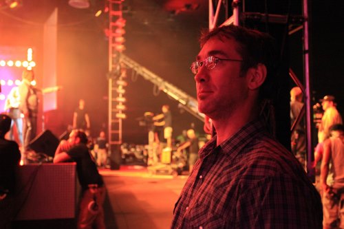
With Robert ‘Max’ Maxfield
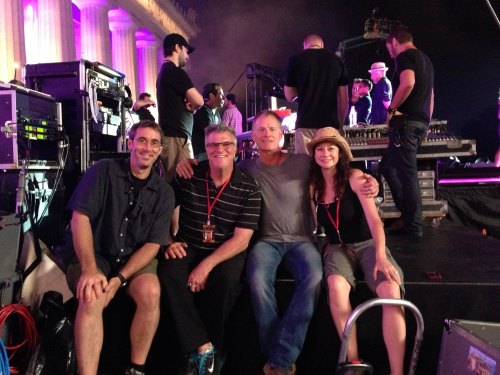
Photos by Gene Page, courtesy of AMC TV, except where otherwise noted
Did you know that chiggers don’t really burrow under your skin?! Nope, actually they grab onto a hair follicle, and inject a digestive enzyme into your skin cells. The enzyme ruptures your cells so that they can drink the resulting fluid containing a protein they need to grow. Your skin hardens around the area, forming a nice big red volcano-like sore. That enzyme-filled volcano keeps you itching for a good three to four days. And you’re almost never bitten by just one!
I came by this intimate knowledge of chiggers in the early fall of 2011 when I was invited to go down to Atlanta for three weeks to boom a show I’d never heard of called The Walking Dead. It was in the middle of Season Two, and I was told that another guy would come in after me to finish the last five weeks of the schedule. It’s not a good sign when you take over in the middle of a season and it’s even less promising when they’ve already scheduled another person to come in after you. I couldn’t shake the thought that I was just another piece of raw meat for zombie lunch. And the prospect of working nights on a project with blood, guts and gore (I’ve never really taken to B-movie horror) was not attractive. I had memories of working with slimy creatures in the early ’90s series Freddy’s Nightmares and wasn’t eager to revisit the experience. So, after a short deliberation, I told the Sound Mixer, “Thank you for inviting me, but I’m going to have to pass.”
 Well, seven days went by and I still hadn’t booked anything for the following week, so I thought, “Heck, three weeks with a bunch of rotting corpses in sunny Georgia couldn’t be too disgusting, and it’s not like I have to eat lunch with them.” Like any Boy Scout film worker during lean times, I called the Sound Mixer back and asked, “Still looking for a good Boom Operator?” He said, “Yes, come on down.” I shook off the disquiet that they were only three days from needing someone and hadn’t yet filled the position. “Oh well, they’re paying me housing and per diem, plus a box rental and rental car … I’m outta here!”
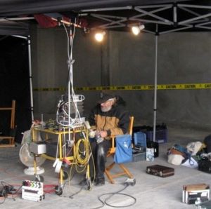
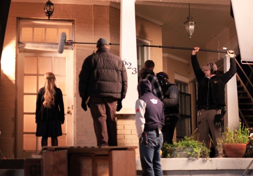
Three days later, I was driving my rental car down a pitch-black country road at six o’clock in the morning, just outside the tiny rural town of Senoia, Georgia. The stages are situated in an old chemical plant on a dead-end road, one hour south of Atlanta in a thickly forested area that only chiggers could love. It’s shrouded by trees, stagnant ponds, railroad tracks and all of the little creatures that make for a great horror flick. I fought off the feeling of this being my worst nightmare.
I arrived to some good news. They told me that I was the ninth Boom Operator on the show since its inception a year prior. “You mean that in only 13 filmed episodes, you have been through nine Boom Operators!” “Yep,” the Sound Mixer said. This was not sitting well with me. By the end of that same Season Two, they would reach the milestone of 11 Boom Operators! To this day, they call me “Number 9, Number 9, Number 9…” There have also been several Mixers over the seasons, starting with my friend and supporter, Bartek Swiatek, CAS, a Local 695 colleague who left Georgia to move to California, and coming to the present day with Michael Clark, CAS.
 Oh, and it turns out, I did have to eat with those zombie things. Nothing like lunch with a gooey corpse sitting across the table from me, spoonfeeding itself through displaced dentures into its black-and-blue prosthetic face—yummy. But, it’s those little tufts of half-dead hair that really creep me out.
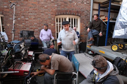
The day before my arrival, they had filmed the Season Two farm scene where Rick, Shane and the others, slaughtered the zombies that Herschel’s family had secretly kept in the barn. Our first setup had 12 cast members, spread 12 feet apart outside the barn, shuddering over the deaths of their kinfolk-turned-zombies. There were three cameras (a daily ritual) on three separate 30-foot lengths of dolly track that formed a large U around the actors. All of the cameras had long lenses. I was the solo Boom Operator, as the six remaining tracks on the Sound Devices 788t were allocated to the scripted speakers and the mix track. It was my first day with this Mixer, so I hoisted the boom, danced about the dollies and stretched with determination to prove that I could get some dialog; I wanted to stand out amongst the eight previous Boom Operators. My results seemed feeble, as I was only able to get a couple of lines. The Camera Operators and Dolly Grips were giving me funny looks like “What’s with the new guy? What number is he?” “Not the last,” said someone, “he’s walker bait … won’t last a week!” They all chuckled. What the hell had I gotten myself into?
Far in the back of the acting pack was Emily Kinney (playing Beth), who sobbed uncontrollably throughout the scene. She was not wired but she dominated each take with her emotional outcries. I mentioned that it would be best to pull a wire off someone that I could get on the boom and put that wire on her but there was no enthusiasm for taking the time to make the transition. As the third take commenced, a loud jet entered the shooting zone. I immediately called for a hold, but the 1st AD cut me off. “We don’t hold for planes … roll sound!” The remaining three weeks of my stay were grueling, sweaty and filled with my first set of fluid-sucking chiggers.
 Later, I learned that, due to time constraints, upper management restricted freedom to make corrections. The production schedule was so relentless that, at one time, they had adopted a policy of using radio microphones exclusively. They didn’t ever want to see a boom over any actor and were determined to fix any sound problems in Post. The Sound Mixer went on to tell me stories about how they would wait for “Roll Sound,” get the sticks and then, at the last second, slip the boom in for some of the close-ups.
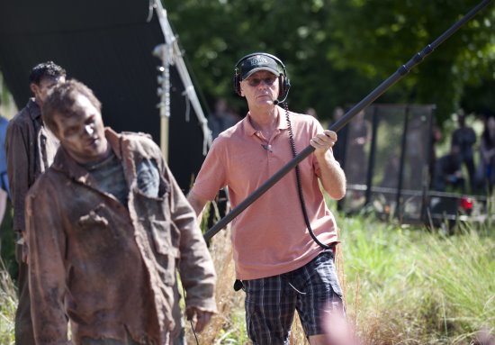
The history of booming this show aside, there was a lot of pressure on me to boom some scenes because of challenges with wind, wardrobe, props and the active nature of the staging. One night, I had to boom a scene that took place in a tent. Both of the characters, Rick Grimes (Andy Lincoln) and Lori Grimes (Sarah Wayne Callies), entered the tent while talking and then disrobed and continued with their dialog. It was impossible to wire them, so I had to figure out a way to boom them in the tent. Do you have any idea how much space is available in a tent after two cameras, two operators and two assistants have been employed? Add in four apple boxes and two 4-foot sliders, and it’s really cramped. The only thing going for me was that they had to raise the side flap to position the cameras. There was barely enough room for me to insert a 12-foot boom pole with a Schoeps MK41 capsule on a GVC. I had to start the shot crouched down, yet standing, so as to reach the tent’s entrance. Fortunately, I was able to aim the microphone straight through the fabric to bring them into the tent talking. I was just millimeters from the cloth ceiling, so I had to be extremely careful not to whisk the microphone on the cloth, while keeping it equidistant to their mouths. After they entered and began taking off their clothes, I had to back up and get down on both knees. At one point, Rick delivered a couple lines looking away from Lori. I couldn’t possibly get them both, so I put a plant microphone on a nearby table, and boomed Lori until Rick turned back. The plant did its job. It was four o’clock in the morning, the last scene of the night, and I was exhausted. It was truly my best booming feat during the entire three weeks. But, as the Camera Operator, Michael Satrazemis, said that first week, “It’s a tough show, but that’s what makes it great.”
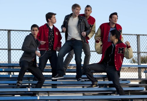
 Obstacles and frustrations aside, I figured I better work hard, have patience and keep a good attitude. The actors were fabulous and supported my efforts from the beginning. In fact, I remember the Sound Mixer telling me, when he was trying to entice me to do the show, that the actors were very warm and accommodating and kept him motivated to do good work. People like Andy Lincoln (as Rick Grimes), Norman Reedus (as Daryl), Scott Wilson (as Hershel), IronE Singleton (as T-Dog), Jeffrey DeMunn (as Dale), Lauren Cohan (as Maggie) and Steven Yeun (as Glenn) would come up to me and give me a good-morning hug. I hardly knew these folks, and they welcomed me like family. Jeffrey DeMunn said it first, and he said it the most, “WE are the Walking Dead” WE, the cast, crew and abovethe- line executives, ARE THE WALKING DEAD! It’s still true of the cast to this day. The Georgia heat, the remote locations, the grueling production schedule, the absence of zombie hygiene and chiggers, make this a very difficult show, but the spirit the actors bring to the project keeps the crew working together as a team.
Yet I still wasn’t convinced that I wanted to be a part of it when I was asked to join Season Three full time. I had doubts, so many, in fact, that I said, “NO.” I continued to say, “NO” for about four weeks. The thing that really turned me around was the fact that the Sound Mixer went to the wall to get me a rate I couldn’t refuse. Yep, it came down to money. But now, after two full seasons, I look back, and I look forward, and I confess, it isn’t the money that makes working on The Walking Dead worth it, it’s the family spirit. It’s the excitement of being part of one of the most amazing TV shows ever.
The setting of this TV series is unique in character, in that it takes place in a post-apocalyptic world. There is no electricity or running water, no trains, no planes, only a few cars and so far, no boat. We do have one obnoxious motorcycle, and usually we can get Norman (as Daryl) to turn it off before he speaks, but sometimes this is logistically impossible. A post-apocalyptic world is a quiet world. But, we shoot in rural Georgia. We have highways, lots of trains, farm implements, bustling towns and our studios are right in the approaching pathway of Atlanta Hartsfield International Airport. It’s not easy recording dead quiet takes in our modern world.
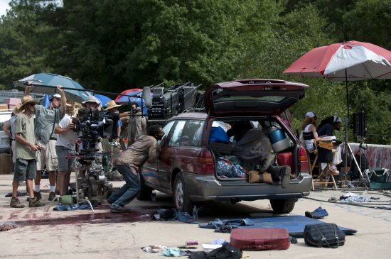
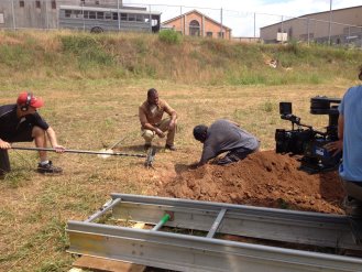
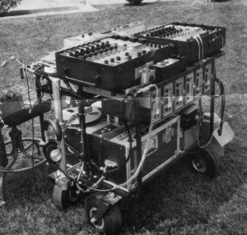
Locations are often deep in the woods, on rarely traveled dirt roads, abandoned railroad tracks and around brush-shrouded ponds. This means that we have to load our equipment onto flatbed trailers and get pulled by four-wheel-drive vehicles to our locations. When the going gets rough, we all pitch in to get it down. And when a deluge of rain comes in, we all take the hit on another sloppy mud fest to get ourselves out of the swamp bog.
Many of these locations lay along the unused rail tracks that serviced the now-abandoned enterprises in this part of rural Georgia. The Construction Department built several wooden carts to help move gear along the tracks. They’re very helpful when they work but they often break down and we’re forced to remove our carts and roll or drag them along the gravel rail-beds adjacent to the tracks. Zombie apocalypses don’t generally occur right next to the Walmart so we often need to haul the gear a considerable distance. That the carts are wobbly and tend to squeak doesn’t really bother us except when they are pressed into service as camera dollies. Then the noise of the cart layered with the sound of grips pushing it on the gravel rail-bed does make recording a clean track difficult.
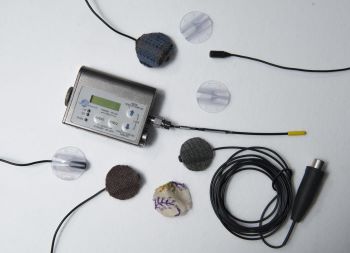
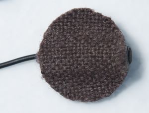
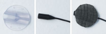
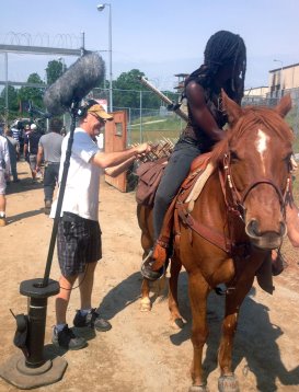
Actors on The Walking Dead roll around, run, shout, yell, fight, whisper, snap their heads from one side to side, kneel, bend over and swing lots of props (guns, knives, katanas, crossbows, backpacks, hammers, crow bars, bottles, etc.), all in the same setup. And, they do it amongst trees, vines, creeks, tall grass, railroad tracks, rubble, fences, furniture and the like. This constant activity makes booming the show a unique experience; my legwork has never been more tested. The dizzying array of props needed to combat zombies forces us to be creative in radio microphone placement. We’ve rigged collars, hats, hair, the props themselves and everywhere else imaginable.
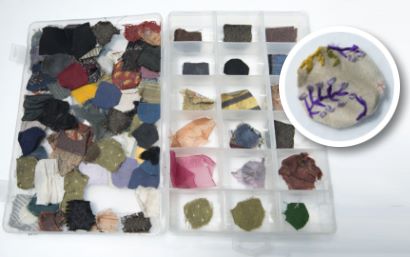
Anyone who has viewed the show is well aware of how location-driven the sets are. We work in the forest a lot. We work on gravel roads a lot. We work in fields a lot. We work with the elements a lot. But we also work a lot indoors. The difference is, 99.9% of our locations, wherever they may be, are filthy. They’re dusted, shredded, destroyed, trashed, wetted, burned and pillaged. Everything is dirty on The Walking Dead. The only good thing, as far as sound goes, is that the mills and plants that serve as our sets are typically vacant and out of business. Turning off noisy appliances is not so much an issue with us. But, the sheer volume of filth complicates placing microphones on the actors. In fact, the costumers go to great lengths to pat them down with blood, dust, dirt and oil. Blood and oil are the real test. And this show really uses blood—lots of blood—gallons of blood. In fact, there’s something like 10 types of blood: live blood, dead blood, real dead blood, drippy blood, gooey blood, thick blood, blue blood, black blood, it’s bloody unbelievable! As much as we all love Joe’s clear butyl, it doesn’t work on bloody and oily clothes. Perspiration doesn’t make such a good friend either. We end up having to sew most of the lavaliers into their clothes, especially during the warm months. This takes extra time. Fortunately, over the seasons we have conditioned the production staff to bring the actors to us extra early. Unfortunately, they have to be un-sewn whenever there is a technical issue with the lavalier, or when there is a wardrobe change. To avoid the need for re-sewing, we do tests, placing the microphone in the proposed position and having the actor go through anticipated body motions. Sometimes we’ll wire additional wardrobe in advance. We’ve wired as many as three shirts at one time. On this show pre-planning is imperative, because we almost never do rehearsals, and time is so precious. Then, at wrap, the actors must come to us after a grueling day of rolling and fighting their way through the zombie apocalypse to have their microphones extracted from their costumes.
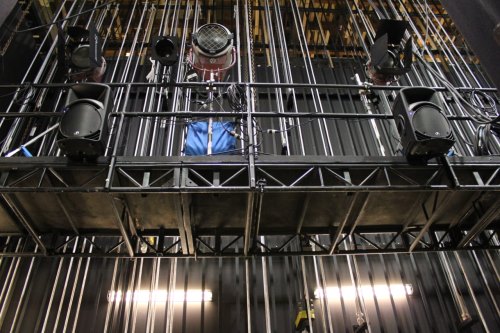
The sun provides its own little challenge. Ordinarily, “fly swatters” (20 x 20 diffusion frames rigged onto an overhead condor) would soften the shadows on exterior shots but they aren’t used on The Walking Dead. The difficulty of getting that kind of gear a quarter mile down rail tracks to a shooting location precludes their use. Sometimes this forces us to use two booms to capture shadow-free dialog from a single player.
Much of The Walking Dead is shot in the summer. Georgia is sweltering hot with singing cicadas, croaking frogs and stinging sunburns on the back of your neck. Every time I wring out my shirt, I have occasion to remember the line from David Lynch’s Wild at Heart, with Laura Dern and Nicolas Cage, “You’re as hot as Georgia asphalt.” Summer is when the chiggers, ticks, mosquitos and spiders are most plentiful. Sometimes, before we even arrive on set, we drench our bare legs, arms, necks and midsections with a not-so-healthy dose of DEET. It stings a bit at first but really does the job. We don’t like it, but it beats scratching for days on end until your flesh comes off. Ahhh, the glamour of Hollywood.
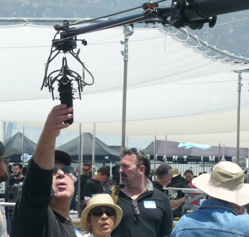
The Directors and Directors of Photography make full use, as they should, of all the visual tools at their disposal. They use Steadicams, Go Pros, DSLRs, below-ground positions, hidden cameras, long custom- made sliders to go among vines and trees, high-angle crane shots and every device imaginable to achieve an expressive image. Typically, several of these elements will be combined for multiple views of the action. This adds to the challenge of getting good dialog tracks.
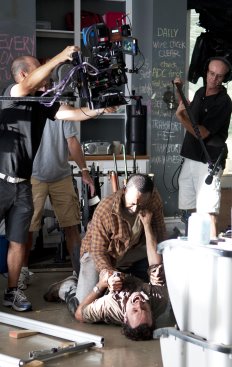
 Episode 405, “Internment,” is illustrative. The Director, David Boyd, one of the former DPs on the show, believes in guerrilla-style filmmaking, using multiple cameras in obscure positions. The episode took place mostly in the prison cells, where Scott Wilson (Hershel) would tend to the near-death patients. These cells are really only about 10 feet by 10 feet with a bunk bed on one side. Director Boyd staged the scene with three actors, three cameras and two operators. Radios couldn’t be used because the actors had blood on their chests and air masks on their faces so my assignment was to squeeze into the cell with everyone else and get the dialog. My regular position in these scenes was either standing on the upper bunk or squeezed between an operator and the wall, only inches from the talent.
These same cells presented one of our biggest acoustic challenges. Although they were prison cells, and ought to sound like prison cells, they were really made of wood. We used furniture pads on the walls, and acoustic tiles in the corners when they wouldn’t be seen, but many times we couldn’t control things. Fortunately, the reverberant effects that Post Production added fixed the problem, and made for some very interesting character effects.
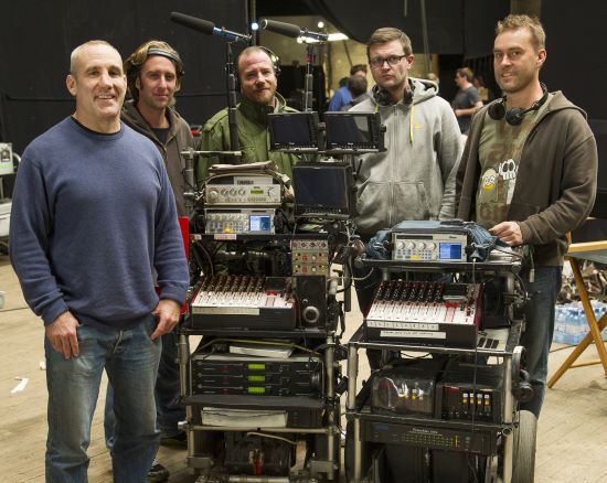
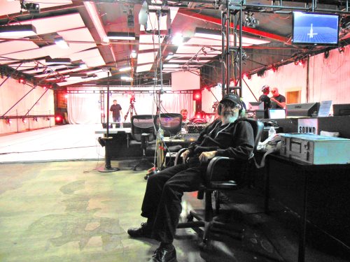
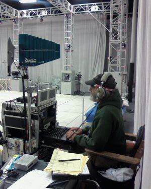
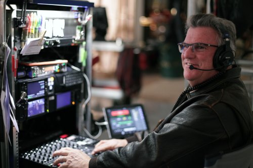
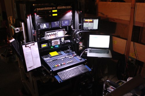
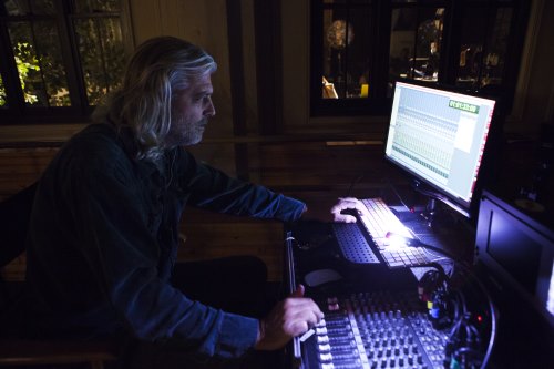
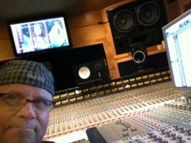
Despite these extraordinary elements, the soundtracks have been getting better and better. This is due to a solid proactive plan, teamwork, ample first-rate equipment and excellent execution. Production Sound Mixer Michael P. Clark, CAS leads us through the process by being very involved. Days in advance he will be analyzing scripts, talking with decision makers, preparing equipment and contemplating solutions. And his mixing skills are sharp, clean and logical. Dennis Sanborn, the Utility person, is assertively proactive in preparing equipment, securing locations and most importantly, wiring all of the actors. He is both skillful and resourceful. As arduous as recording sound is on The Walking Dead, these guys step up to the challenge of working on one of the most difficult shows in television with grace and determination.
I’ve never before been part of something so deep, difficult and complex as the process of making this show. More than any project I have ever worked, the shared sentiment that “We Are the Walking Dead” makes this one of the most remarkable career experiences that I have ever had. It has truly changed my life … and my career.

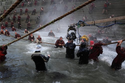
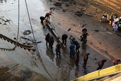
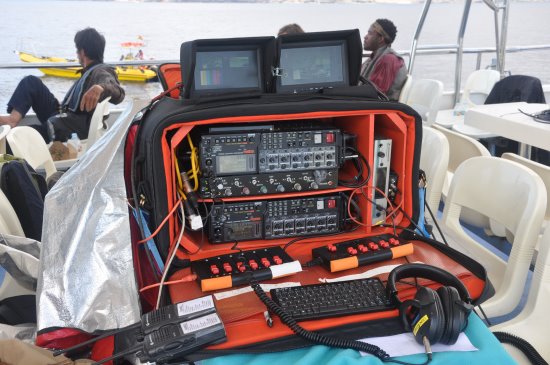
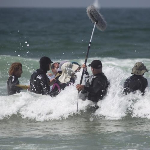
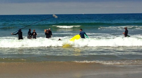
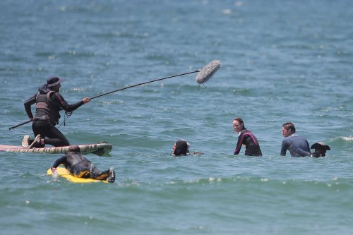
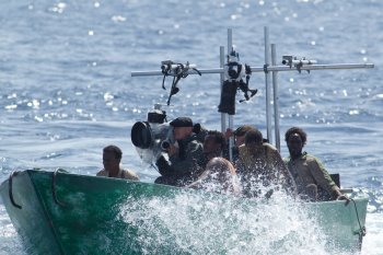 Having worked on five James Bond films, I was no stranger to action sequences involving water, especially the boat-chase sequences on Quantum of Solace filmed in Panama. On Captain Phillips, I needed waterproof lavalier microphones that also sounded good out of the water so I chose to use Da-Cappo DA04s (now Que Audio performance series in the USA). These are very popular in theater because of their very small size but have great waterproof qualities due to the inlet size being smaller than a droplet of water. I mounted them upside down so that no water settled on the microphone. I had to develop a system for getting longer range reception for recording in the high-powered pirate skiffs. I used Audio 2040 mini-tx radios in aquapacs on the pirates. The receivers were built into secret compartments in the skiffs where audio was recorded and re-transmitted to the bigger boat that we were all on. We were regularly recording up to 16 tracks and feeding a mix to Video Assist, the Director and Camera Operators. I recently wrapped on Heart of the Sea, with Ron Howard where again I was able to use what I had learnt. Months before I started on the film I said to the boat builders, “I need you to build these secret compartments…”
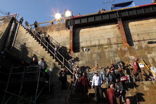
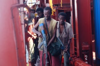 On Captain Phillips, we were based in Malta on a container ship, which was our studio for much of the film. Each department had a base in one or more of the containers to store equipment and carry out any maintenance. We still needed to be highly portable as we would shoot inside the ship, perhaps in the engine room or cabins while heading out to sea and returning to port, and shoot on decks and the bridge when at sea. There were a lot of stairs, and some passageways were very narrow. Generally, we were shooting multi-camera without rehearsals and all with improvised dialog, sometimes with the scene playing out between several groups in different parts of the ship.
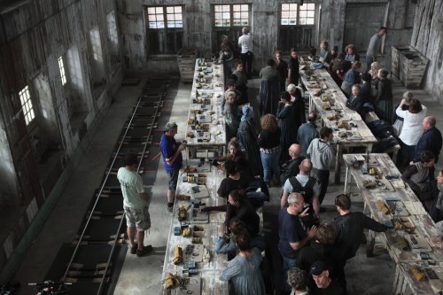
 Oliver Tarney was Supervising Sound Editor. I had also worked with him on United 93 and the two Sherlock Holmes films with Guy Ritchie. One of the best things we were able to do was to get Oliver to spend a weekend with us on the ship recording sound FX. Not only did he get the FX that he needed, but he also got to experience the ship and to understand how it should sound at sea and its geography. He also got to experience being in the lifeboat—known by us as the vomit vessel—certainly not a pleasure craft!
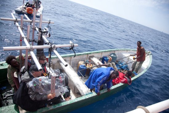
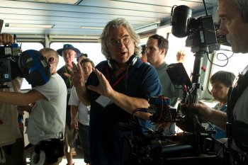
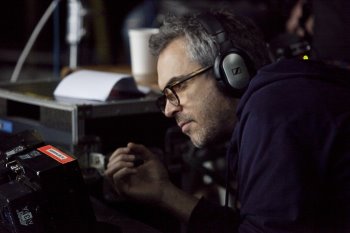
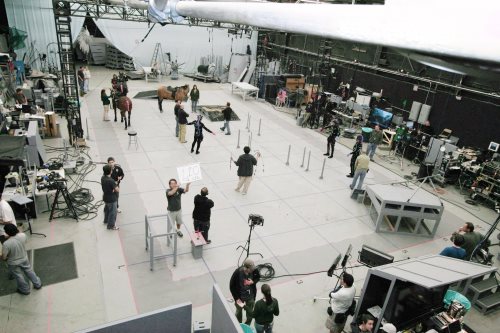
 Gravity was a completely different experience from anything I had previously worked on. When I first got the call and was told that there were only two actors in the film and that there is no sound in space, it sounded like the perfect job! Then when I met Alfonso Cuarón and he started to talk about his ideas for the film, I was hooked and immediately knew that this was going to be something special. Every few years there is a film that breaks the technological boundaries— this year it was Gravity. The first issue was that both the cameras and the actors could be on robotic arms. I had recently shot a small sequence with these and knew that, although the arms could move with not too much noise, the associated power supplies and controllers were very noisy. So the first job was to negotiate that these could be extended and built into blimps far away from the action.
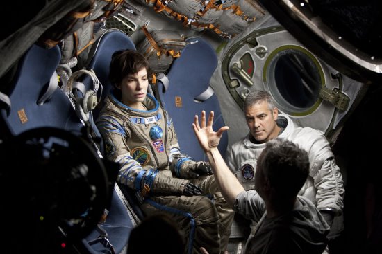
 Alfonso Cuarón originally had a plan for all of the radio conversations and OS dialog to be live, and we had planned to have different rooms in the studio for those to be performances. However, due to artist availability and other issues, this proved to be impractical so we prerecorded as much as we could. Most of the pre-records were guides that were re-recorded as ADR in Post Production.
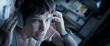 Here was another opportunity to use the Da-Cappo microphones— this time because of the very small size. The microphones used were a mixture of a Da-Cappo capsule that Jim McBride, our tech support engineer, had fashioned to an arm connected to the inner helmet and a latex shield that we made for both visual accuracy and to reject noise from outside the helmet. A second Sanken COS-11 was sewn into the inner helmet as were earpieces for communication. We also had in-ear molds made for some scenes. Each different piece of headgear that Sandra Bullock wears in the film contained practical microphones and earpieces. Even the classic Russian headset that she uses at one point has a built-in transmitter and receiver. We achieved this by borrowing bare 2040 mini-transmitter boards from Audio Ltd. and building them in to headsets.
 The Director and the 1st AD needed to be able to communicate with the actors and DP, Camera and other departments without distracting the actors when giving technical cues. The costumes and helmets so completely isolated the actors that they needed an audio feed both to hear each other and also to hear their own voices. Allowing them to hear themselves, but at a reduced level to avoid distraction, required a second layer of IFB feed to each.
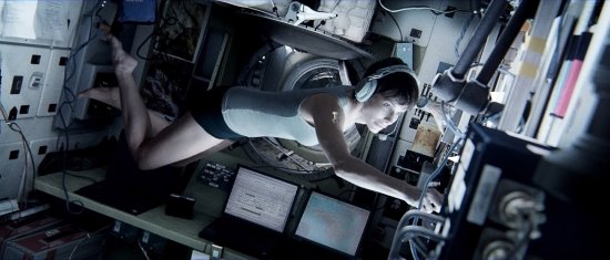
 If MoCap is to be used on the actors’ faces, smaller, BB-sized reflective spheres are glued directly to the skin, sometimes in the hundreds. When too many have fallen off, work stops until they can be replaced, a process that takes some time because they must be precisely positioned.
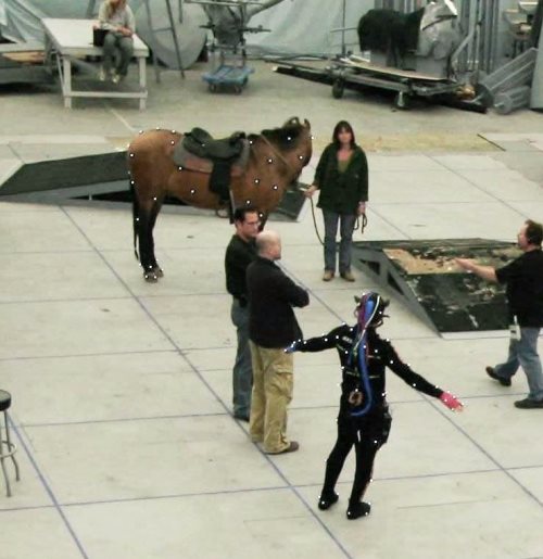
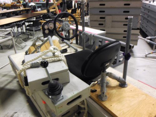
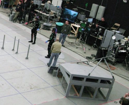
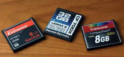
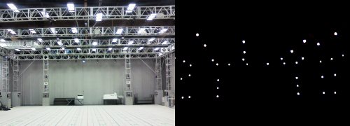
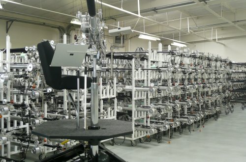
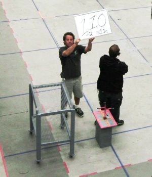 Multiple conventional HD video cameras are used in the volume for “reference.” These cameras cover the scene in wide shots and close-ups on each character. This allows the Director to judge an actor’s performance before the data is rendered into the animated character. A secondary function is to sort out body parts when the MoCap system gets confused and an arm sprouts out of a CGI character’s head. Looking at the reference shot, the Editor can figure out to whom it belongs, and mouse-drag it back into its proper place. In most stages, the cameras are hard-wired into the system so they have house-sync TC and do not normally require TC slating. They may use DV cassettes and/or send the video directly into the system.
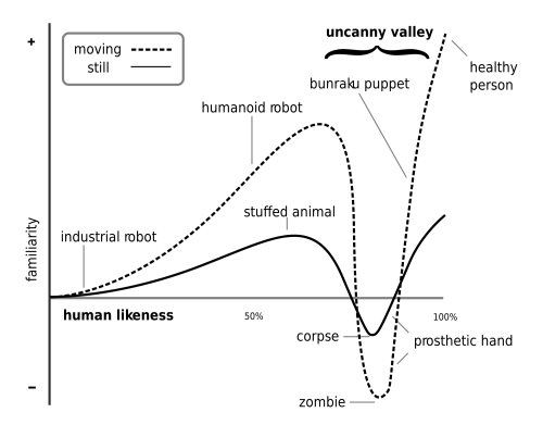
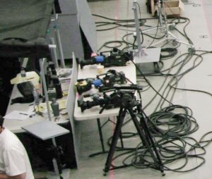 A graph of the “realism” of a character versus its acceptability starts at the lower left with obvious cartoon figures and slowly rises as the point moves to the right with increasing realism. But before the character’s image reaches a peak at the right edge, where photographic images of actual human beings fall, it turns sharply downward into the valley, and only climbs out as the character becomes “photo-realistic.” Even an image of a real human corpse (possible disease transmission) is in the valley, as would be that of a super-realistic zombie.
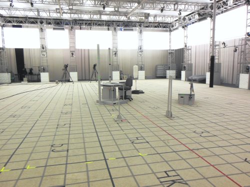

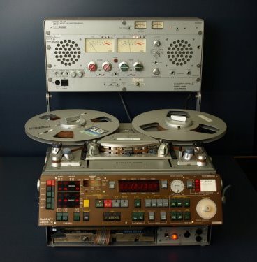
 James E. Webb Jr. is justifiably renowned for his work developing multi-track recording on a series of films for Robert Altman. He captured the dialog from multiple cast members and interlocking story lines on such iconic films as Nashville, Buffalo Bill and the Indians, 3 Women, and A Wedding. He pioneered the multi-track process.
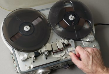 Editor bringing down this big box of about 50 seven-inch reels and us sorting through them. Then Mark announced he wanted to do the master shot all the way through. Duke Marsh, who was doing the playback with me, grabbed a second Nagra and we loaded the first part of the desired mix of the song on Nagra 1, the middle of the same song on Nagra 2, and stood by holding the pinch roller ready to let it fly on Playback. As Nagra 1 was playing, we had to start Nagra 2 at the correct spot and then, while it was playing, reload Nagra 1 with the end of the desired mix. I remember Mark Rydell came up to us after our successful playback day and said he wouldn’t do that job if someone held a gun to his head.
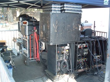 For this reason, in 1993 I switched to Pro Tools, a nonlinear computer-based system. If we had been using Pro Tools in 1990 when we did For the Boys, we could have loaded all the various playback combinations into one session and been happy clams. Pro Tools (computer-based recording, editing & playback) was vastly superior to tape systems as far as “function” (ability to manipulate the audio), although not necessarily “performance” (sound quality). It took a while for the computers to catch up with the sound quality of a Nagra; however, for playback applications, the tradeoff between function and (audio) performance was decidedly biased toward function. This is why the computer-based system (Pro Tools or similar) has become the de facto standard.
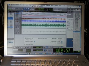 On Drag Me to Hell, a séance scene required reverse playback of the actors’ live lines. These effects could not have normally been done on set with a tape-based system.
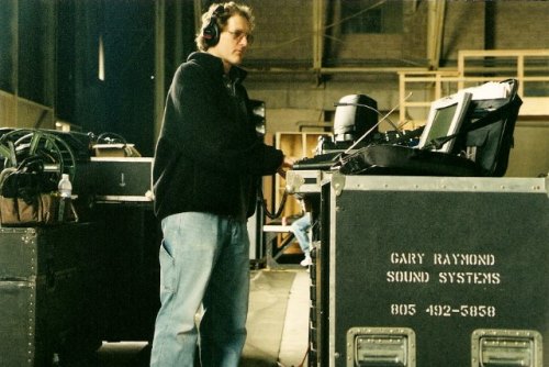
 As a Local 695 professional, we hear a lot of crazy things at work and no, I’m not talking about that sick old generator staring at you fifty feet from set.
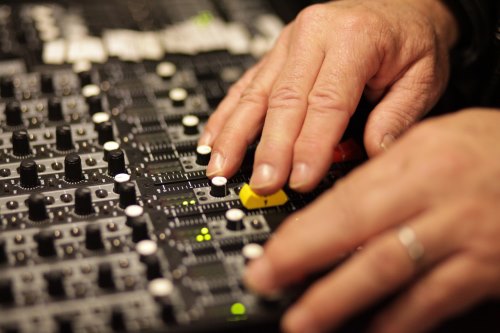
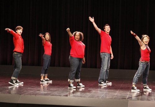
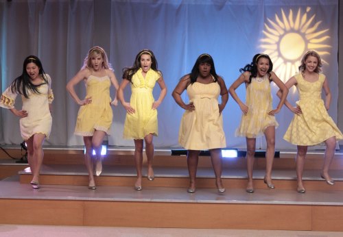
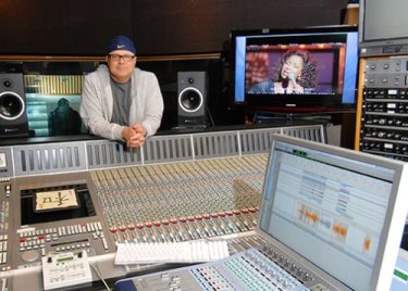 How a production approaches the pre-record sessions influences the success of the whole venture. A good pre-record session should take place with awareness of how the scene is to be shot and the pace of the performance should mesh with the demands of dancing, screen action and other visual elements. Ideally, the same singers who appear on camera should record their own performances for playback (PB) tracks. It’s more natural for actors to match their own performances rather than a hired studio singer. The transition from dialog to music to dialog is more believable if the voice is the same throughout. And, if done well, the pre-record functions as a first rehearsal for the scene. It should be executed long enough in advance so that the musical performance can “season” in the actor’s brain for at least a few days.
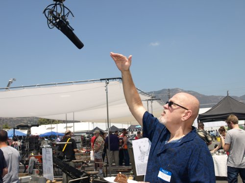
 In 2010 and 2011, I spent autumn in Beijing, China, at the BIRTV (Beijing International Radio and TeleVision) trade show, courtesy of John and Nina Coffey and some of the companies they represent. I was looking forward to going back again in 2012, but alas, it was not to be. Probably because of my telling all and sundry what a great time I had before, the owner of one of the companies that defray my expenses decided to go himself instead of sending me.
 1. The wrap party for my Da Nang class was held at a local restaurant. When I arrived, all the students were there, seated at a long table. I was greeted by a large poster with my picture, and my name spelled correctly (unlike China, where a large red banner read “James Tanen Baum” and my exhibitor’s badge had yet another misspelling).
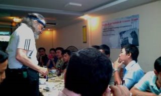 “Imagine you are at the beach, and the tide is coming in. If you stick a surfboard in the sand and stand behind it, will your feet get wet? Of course they will, because the water will simply wash around the narrow obstacle, just like low-frequency sound will. And when the waves crash against the board, they will knock it down even if you try to hold it upright, just as low-frequency sounds will push and pull on a flimsy wall to pass through it. (Actually, the original sound waves will be stopped by the wall, and new ones generated on the other side, but you get the idea.)
 “How much you give?” Never, never, speak a recognizable tongue to a street vendor.
 Never, never, never buy something from a street peddler. She held out the remaining caps.
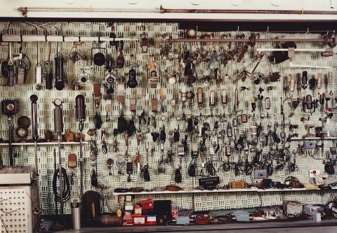
 I was starting to write my experiences with the Nagra and was thinking only of the model III and then it occurred to me that my earliest experience was with the Nagra II. I had just graduated from high school and was working at the new listener-sponsored FM radio station in Los Angeles, KPFK.
 It was late 1968 and I had been working for about nine months at a big L.A. ad agency, running their small recording studio— voiceovers, radio spots, etc., on big old Ampex 351 ¼” recorders. I had no real idea what I was doing but, compared to what those ad agency folks knew, I was a damned genius—some things never change. Anyway, I quickly grew tired of that and began looking for other gigs. I recorded a few bad rock and roll bands at various studios around Hollywood, but even at that young age, quickly burned out on the late nights and long hours spent indoors. Someone suggested that I get into movie sound—often done in the daytime and outdoors, every shot being different, and the pay wasn’t too bad either. Before I knew it, a trusting fellow from New York named Jim Datri handed me an elegant-looking metal box called a Nagra III, a converted Bolex mono-pod with a Sennheiser 404 on the small end plugged into a KAT-11 preamp, and a set of Beyer headphones which seemed to weigh about 13 pounds. To my studio-inured eyes, the whole rig looked like some sort of arcane scientific testing apparatus. Suddenly, I was in charge of recording sound for a motocross documentary, lugging the thing over hill and dale someplace in the depths of Orange County—and tethered to a 16mm Arri S by a sync cable, like the ass-end of a donkey at a costume ball—as dirt bikes roared around us menacingly. Good thing I was only 21 years old…
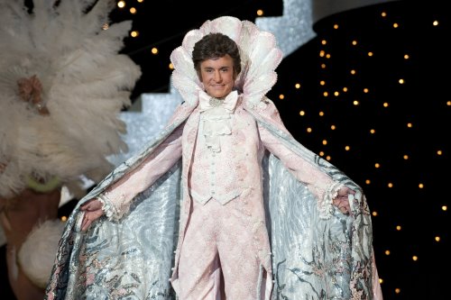
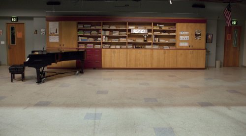
 Soderbergh has his own style of filmmaking: most importantly, he likes things to be real. With this project, that meant many practical locations and sets full of mirrors. And not the “set mirrors” that you can gimbal; they would be real. And often quite large. And reflective surfaces would be the norm for almost every scene. Even Liberace’s piano and clothing were reflective. Oh, and there would be musical numbers, some involving complicated vari-speed playback and other fancy tricks.
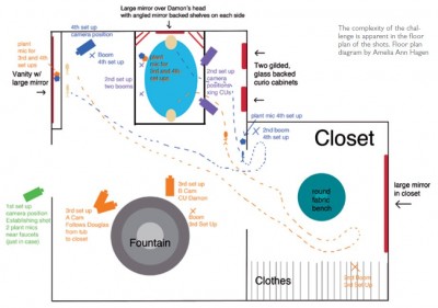
 We shot many scenes at the LVH in Las Vegas. The set designers and their crew meticulously dressed Liberace’s penthouse to look as it did back in the 1970s when it was called the Hilton Hotel in Las Vegas. Did I mention Liberace’s love of mirrors yet? The very last scene we shot in the penthouse was another of those of those scenes where we would have no choice but to rely mostly on the wires.
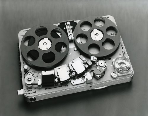
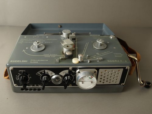
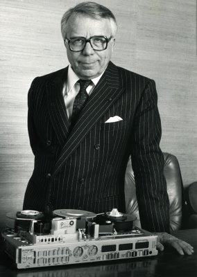 Long considered the “gold standard” for location sound, the Nagra recorders established a level of technical superiority and reliability that to this day is unmatched by almost any other audio recorder (with the possible exception of the Stellavox recorders, designed by former Nagra engineer Georges Quellet).
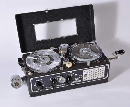
 Acceptance of the Nagra III was almost instantaneous. 240 machines were built in 1958, and in 1959, the Italian radio network RAI (Radio Audizioni Italiane) ordered 100 machines to cover the Olympic Games in Rome, paying cash in advance. With this rapid expansion, larger premises are acquired in Paudex (near Lausanne). Since the Nagra III relied heavily on custom machined parts, a significant investment in machine tooling, along with skilled machinists to run them, was required to keep pace with orders that were now coming in from networks around the world, including the BBC, ABC, CBS, NBC and others. By 1960, there were more than 50 employees working in Switzerland, and a network of worldwide sales agents was established to support the sale and service of the machines.