Report from the Young Workers Committee
by Eva Rismanforoush
Occupational stress has long been acknowledged as a serious health hazard in the industrialized workforce. It is as an underlying factor of hypertension, cardiovascular diseases, diabetes, substance abuse, and it does not distinguish between ethnicity, gender or class. Workplace stress is also directly linked to chronic psychological disorders such as anxiety, panic attacks and major depression. We are often exposed to extreme weather conditions, environmental and health hazards that can range anywhere from rattlesnakes, structually compromised buildings, airborne pathogens and hazardous chemicals, etc.
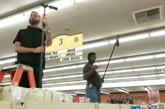
As members of the entertainment industry, we face some of the most adverse jobsite conditions and hours in the developed world. We spend seventy-plus hours a week on set during a regular TV season or a feature film. We are often exposed to extreme weather conditions, long hours, environmental and health hazards that can range anywhere from rattlesnakes, structurally compromised buildings, airborne pathogens and hazardous chemicals, etc. But we work because it is a central part of our lives and we creatively thrive through it. However, as exhilarating and interesting the job may be, the sheer magnitude of daily logistical efforts and close personal interactions can cause stress.
Our bodies are equipped with a natural coping mechanism, which is activated when a potentially dangerous situation is detected. It is called the “fight or flight” response. It always proceeds in the same manner: the danger stimulus, the removal of the danger and a state of relaxation.
While this mechanism has been crucial to our survival as a species, it is designed to only activate in isolated instances. “Fight or flight” served our ancestors well as they fought off natural predators. Yet as the developed world becomes increasingly safe for humans, the American Psychological Association reports that stress levels in the twenty-first century are higher than ever.
Today, many of our stressors come in a much subtler form and stem from a broad variety of factors. Whether it is increased productivity demands, muscle strains from booming increasingly long digital takes, dealing with trying personalities or never being appreciated for the quality of work we produce. All of these causes can trigger a “fight or flight” response. But we got so used to working in demanding environments that we may be unaware of the body’s reaction. And whether we are aware of it or not, the constant “on-alert” state is cumulative and takes a toll on our physical and emotional well-being. Bruce McEwen, a neuroscientist at the Rockefeller University, recently revealed that exposure to three weeks of stress can change mammalian brain-architecture. Forcing his rats to swim, among other adverse activities, shrank the dendrites in their amygdalae, the parts of the brain that control emotional responses, decision-making and memory. Some of these effects are reversible, but such changes increase the risk of anxiety disorders and depression. McEwen also linked chronic stress to a reduction in the overall neuron number.
WHAT IS STRESS?
Stress is a household term used to describe a hormonal surge in our bodies resulting from physical and mental strain in adverse circumstances. Hans Selye, Director of University of Montreal’s Institute of Experimental Medicine and Surgery, first coined the term stress in his letter to the British journal Nature in 1936. Selye’s “general adaptation syndrome” (GAS) study, which was later renamed “stress response,” revealed morphological changes in mammals due to prolonged and excessive secretion of naturally occurring stress hormones.
COPING WITH STRESS
Our bodies are vastly resilient while malleable to the environment. Neuroplasticity, the ability of neurons to reorganize to compensate for injury and disease, allow us to recover to some extent. Kelly McGonigal, Psychologist at Stanford University, suggests that altering how we process stress determines its detriment or benefit. Living without it is improbable, but learning how to use it to your advantage can lead to an overall healthier & happier existence.
This means ending a stress cycle in rest and recovery, whether by not checking emails & social media on the weekends, taking more holidays or going for a walk in the middle of the day. In the right mindset, stress can even be performance enhancing.
Even Hans Selye distinguished stress reposes into “eustress” and “distress” later on in his career.
But how do you get there? We thought it best to harness the knowledge from some of our most esteemed colleagues, who have been in this line of work for decades. They have all found engaging ways to process stress and lead healthy and productive lives. Here are their thoughts, please enjoy!
= = = = = = = = = = = = = = =
“The job itself comes with built-in stress because of the fluid nature of it. Home life is hard to keep balanced. Early on, I had to make the choice to accept these conditions completely or not. Once I chose, I committed. Having committed relieves much of the stress and making sure that your loved ones know that you are not the boss of your time can help relieve potential stress. On the job, I always prepared for scenario A, B, C or the unknown. I operated from a position of being ready for anything at any time and not letting it ruffle my feathers if things changed, because, they always do. Pull a rabbit out of a hat, change a pigeon into a bouquet of flowers. The stress of the job goes away when you accept:
1. You have no control and nothing is predictable
2. You have done your homework even though the call sheet and script can be torn up and thrown out at any time
3. Piss-poor planning makes for piss-poor performance = stress
4. You have all the tools and tricks handy to handle every situation
5. You are able to pull out these tricks at a moment’s notice
6. Never be lazy, always be busy and alert. The minute you slack is when the s**tstorm hits
7. You have the confidence to jump in and do what needs to be done, especially under fire
8. You have accepted the fact that you will be working until they tell you that you can go home
9. Be happy that you have chosen this work every day. No one is holding a gun to your head to stay, so might as well spread a positive attitude so your work environment can be fun and rewarding
10. Realize that there are many people who would be more than happy to take your place
“With all of these things in mind, kick your shoes off and unwind with a glass of vino at the end of a long hard day and try to catch some zzz’s”
– Peggy Names, Boom Operator
= = = = = = = = = = = = = = =
“I’ve always felt that the film business is what you make it. It is intense; there is big money at stake every day. Pressure builds, tempers flare and it becomes cumulative among departments as it spreads down from the top. The trick is, as I see it, is to recognize the tsunami coming your way and prepare accordingly. Certainly, preparation is key. But I’ve always told my assistants that as the production company gets crazier, you get calmer, to the point where you are almost comatose. My dad taught me to ‘work hard and go home.’ I’ve lived that for forty years in the business. It’s worked for me.”
– Randy Johnson, Boom Operator
= = = = = = = = = = = = = = =
“I’ve had many different relationships with stress in my forty years in 695. I’ve dealt with it most every way possible, from alcohol or reefer, to exercise and meditation. I feel the key to dealing with it is to know yourself and to know what stress is. For me, it’s been an evolving relationship through the decades. When I started out, it was like young love and I was high on stress, thinking it was like romantic love, all-consuming and that it would always be like this. It was exciting but exhausting and not sustainable. As the years piled up, I learned to give my all between call and wrap and then shut that door as I got into my van to drive home. This became my time. I dreamed up projects, personal or family, listened to music, anything was cool as long as it wasn’t work-related. For me, it is paramount to have your own life that you maintain and respect as much as your career life. I love family (which can have its own stresses), hiking, playing drums or ukes, painting, photography, fine food with friends, travel and sleep. After all these years, it is easy to keep stress in check when I have a balance of work and play. That and the joy I get from the world-class education I receive observing and marching in the ‘Grand Parade’ of life. It is hard to stress what was or might be if you are actively living in the here and now.”
– Crew Chamberlain, Sound Mixer
= = = = = = = = = = = = = = =
“To get a handle on stress at work, I begin with arriving to set early. Being consistently punctual to your location is paramount and sets the tone for the day.
“Do your homework: Knowing where you’re at in the script and its shooting schedule is a good way to keep the stress monsters at bay. If you know there will be a scene at a waterfall or a big dance number, you will be able to prepare for it and be prepared when it happens. Smaller details like day/night number gives you an indication of costume and wiring changes.
“Taking care: Exercise is another key to fighting stress and yoga has done that for me. It keeps me centered and my attitude in check.
“Nutrition: I will be the first to say, I love pizza for a second meal, complementary food trucks and my morning espresso, but food does have an effect on your mood and your stress level. Moderation is the key and knowing when to curtail the caffeine definitely helps.
“Humor, Thought = Empowerment and Positive Thinking: I’m very fortunate to get to listen to actors act, the telling of jokes and experiencing sublime and scary words and descriptions. For me, humor and just sitting there thinking, leads to a positive outlook about my situation. That leads to empowering my mind and confidence level. How do I get there? I need to be honest with myself and what’s bugging me and deep always clears my head. I can then focus on sound for the scene or try to help others. Wanting to do the best job I can and rooting for the success of others is a direct result of empowering your mind.”
– George A. Flores, Sound Mixer
= = = = = = = = = = = = = = =
“The secret to my sanity is taking my day one moment to the next and not over-thinking it.”
– Lawrence Commans, Boom Operator
= = = = = = = = = = = = = = =
“In late July, I was balancing three major shows for my three biggest clients. I put in 240 hours in 19 days. This included travel, working double shifts, on top of the usual rigors of my job. To add to that, I experienced personal distress, any of which would be a large task to take on with a normal job situation. I remember walking onto the truck, and sitting at my record station, when my gut said, ‘If you don’t take time off soon, you will die. You can’t keep going at this speed.’ I booked a vacation for four days immediately. I went away to a wellness spa in the desert. I turned off my phone for a week, and didn’t tell anyone where I went (except for my mom). Four days was not enough, but it was enough to bring me down from the adrenaline high that I had been riding on for so long, in order to come back and sleep solidly. After that, I decided to take another 2½ weeks off.
“During this time, I realized I needed to create somewhat of a routine. The lack of structure this business lifestyle affords me is not conducive to a healthy lifestyle. Here are some of the things I started to do:
- I started with my diet—I cut down on drinking, carbs, sugars, dairy. I bring all my own food to set with me, even when I travel. The snacks I bring are organic, easy on digestion, yet filling and satisfying.
- I recognize I may not always get eight hours of sleep, but the few hours of sleep I do get, should be quality sleep.
- I routinely see a chiropractor and massage therapist while I’m in town.
- I don’t drink while traveling because it is dehydrating.
- I travel with a foam roller to stretch and work out.
- I always upgrade my seat when flying for more leg room. This is my time to rest when I’m traveling.
- I try to drink a gallon of water every day.
- I try to exercise, which usually means stretching in the morning and evening.
- I always leave the truck for fifteen minutes and walk— seeing sunlight is essential.
- I learned how to quiet my mind.
“Lately, there’s been a focus on small enjoyments of life. When we are constantly go-go-go, you need to take a minute to enjoy life. Find a small joy that takes you out of your day.
“I have had jobs that have caused health issues due to stress, and I’m lucky that I have been able to recover from them. Last year, I went through a breast cancer scare, which made me take a look at my life and examine what I find most important.”
– Jillian Arnold, Digital Asset Manager
= = = = = = = = = = = = = = =
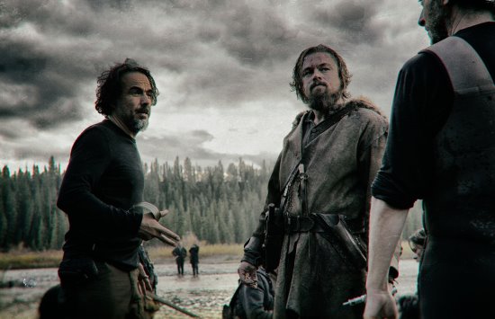
“Stress management and proper set etiquette is really what separates the A-listers from the rest of us. We work in an industry where the creative process often demands to make things happen against seemingly impossible odds. I have been screamed at in my face for issues that were not related to me, I have scrambled around troubleshooting in front of one hundred-plus people all waiting on video to fix the problem and asked to do the impossible over and over. I rarely get yelled at anymore (thankfully), but I tell all the guys on my team that when you do, it’s not personal. There is legitimate pressure rolling down from above. I worked on The Revenant and Chivo, the DP, was incredibly demanding at moments. I just worked with Chivo two days ago on a commercial and it was a totally different experience.
“There are a few tricks that can help avoid unnecessary trouble. I make a practice of introducing myself to the agency on a commercial so if there are any issues with image, they know they can come to me personally to fix it rather than complaining to the producer. It’s simple but it works. Also, communication with the 1st AD is paramount. Newcomers must realize they are responsible for communicating their needs. If you need ten minutes to solve a complex request, you must explain that to an AD. They are your lifeline to make sure the people who matter know what’s happening and to give you the appropriate time.
“No one enjoys the looks you get when the company is waiting for video. I learned that the hard way years ago working with a fantastic director, Rupert Sanders. I was on my first job with him, was brought on by the producer to impress him. She had seen me perform well in many difficult situations so I had credibility with her. Things had been going well until we set up for a difficult choreographed shot with horses, mud and explosions that required a big reset. Just as we were about to call action, the image from the wireless went out and monitors went dark. I intensely wondered what could be wrong as the scene went on. We cut and the director turned and just said, ‘Bye bye, Willow.’ It was in the days of film, so there was no way to play it back and he asked me why I didn’t stop the shot. I was mostly confused & embarrassed that I didn’t make the call and realized right then, it was my job to do so.
“A big part of handling stress is how you recover after a mistake. Often we get blamed for issues that may be camera- or power-related or may indeed be on us as video assist technicians. Sometimes criticism is valid. I despise that moment but handle it by telling myself I am good at my job and trust that by the end of the show, they will see how that moment was not indicative of my normal routine. Professionalism is key and it’s important to remind yourself that everyone is dealing with stress in their respective departments. But what we can do is focus on the job, keep your eye on the ball and maintain confidence. Even if you just threw an interception, you must believe that next throw is going to be a touchdown.”
– Willow Jenkins, Video Engineer
= = = = = = = = = = = = = = =
“1. Exercise—It will lower the toll on your body & has psychological benefits.
2. Hydration—So important & often overlooked. A lack of hydration will cause fatigue and more symptoms that could lead to health problems. By the time you feel thirsty, you’re already dehydrated.
3. Keep learning & pace yourself.
4. Recognize your own signs of burning out: One thoughtless action could ruin weeks of relationship building.
5. Try not to be competitive, but rather, collaborative. The film industry is always expanding.
6. Make personal plans—Even if they have to change a lot; life moves quickly and you don’t want to realize it’s too late for certain things.
7. Be someone others at work look forward to seeing.
8. DON’T overbook yourself. You need “Me” time.
9. Get enough sleep. 10. Choose how you see your job/department on the set; don’t let others make that judgment call.”
– Patrushkha Mierzwa, Boom Operator
Patrick Martens, Boom Operator
& Mark Ulano, Sound Mixer
= = = = = = = = = = = = = = =
“Part of my routine in keeping myself sane and healthy is trying my best to not bring work home with me. Every day is filled with challenges and often annoyances and I think it’s important to check those at the stage door. Home life becomes just that—home life and nothing intrudes on it or its routines. I find the people I’ll be working with and for to be an extremely important factor on choosing jobs. It makes all the difference when the people you work for are good to you. You pay it right back at them. When you are genuinely happy and have a good attitude, it is way less likely that those who work around you who may have a bad attitude to be able to affect you.
“I feel like if we worked fewer hours per day (max twelve on twelve off—but ideally, ten hours call to wrap), we would all be much happier. If I could have dinner at home or out any night of the week I wanted yet still work a full day, I would be even happier. And mind you, it’s not necessarily about the dinner … It’s about the time. If we feel like we have to drive home and rush to bed in order to get adequate sleep before the next shooting day, we end up feeling cheated out of our free time.”
– Devendra Cleary, Sound Mixer
= = = = = = = = = = = = = = =
“Having a family has really made me value every minute I have. We definitely max out our weekends, and while it doesn’t make for a ton of rest, at least I have great memories and a feeling of accomplishment come Monday. Earlier this year, I took four months off and managed my daughter’s fast-pitch softball team and participated in their school events for the first time ever. My husband and I agree, taking care of the kids is much harder than our day jobs (he’s a grip) … So after a stint with the kids, we are actually ready to go back to work. We also always take time off for those precious moments you can’t get back, like trick or treating. It’s important to work with people who also value family or personal time, because it really helps minimize burnout. Taking a day off once in a while isn’t going to stop the show, and it can benefit a fellow 695 member who really needs hours. Win-win!
“One thing I now take more seriously is my health. I no longer put work before annual physicals or illness. Our yearly physical is one of the best benefits of our health insurance, so use them! And if I’m sick, I stay home. Last thing I want to do is make my fellow crewmembers ill. No one is going to think you’re a hero when you’re coughing all over set.
“I love hour walk always. I get outside, walk or ride my bike and rack up some vitamin D. I’ll take care of small errands like washing the car or hitting the Rite Aid. Five lunch hours correlate to a big chunk of my weekend, so if I don’t have to spend it buying shampoo, I’m thrilled. Drinking enough water is always a challenge for all of us, but staying hydrated does wonders for your energy level. Joe Foglia and I remind each other to hit the bottle all day long.
“I absolutely take into account the people I’ll be working with, the type of project, the commute and the season length. Hour-long episodic can be a grind, so unless you’re working with people you enjoy, it won’t work. We spend more time with our work families than our real families. If we can’t have a good laugh once in a while, it’ll be a very long season.”
– Anna Wilborn, Sound Utility
= = = = = = = = = = = = = = =
“I’m fortunate to have relatively little stress in work and life. However, I’m certainly not stress-free. When the stress arrives, the best thing for me, if possible, is to remove myself physically from the situation that is causing it. That can be relatively easy in everyday life but can sometimes be hard to do on set. Usually, I can find a nice quiet corner somewhere to unwind. The timing is the tricky part. Outside of the workplace, playing the drums or guitar has always been a wonderful activity to help me get away from it all and clear my head. However, my absolute favorite all-around tension-relieving, mentalcleansing activity is going for a strenuous run at the beach. It never fails to return me to a tranquil state of mind.”
– Mark Agostino, Music Playback & Live Recording Mixer
= = = = = = = = = = = = = = =
“It is no secret what a difficult business we have chosen. It can be challenging enough just to find suitable and sustainable employment; then, when you get the gig, be careful what you wish for! Long and irregular hours, travel, weather conditions, challenging locations, nasty commute, job security and every kind of work-related stress can take its toll on your health, relationships, mental and spiritual health. Despite the heroic efforts of our dearly departed Haskel Wexler, just getting home from work can be quite hazardous. As a long-term survivor in production sound—thirty-six years since I bought my first Nagra (that’s a little scary when I see it in writing!)—I am very happy to be asked to contribute some ideas about stress management.
“Love what you do, but not to the exclusion of all else; given the crazy number of hours we work, it is hard but important to seek balance in your life. The job can be incredibly frustrating, learn to not go home bitter. That makes showing up the next day a lot easier. On the other hand, sometimes the best thing you can see is that job in your rear-view mirror. Know when to hold ’em and when to fold ’em. There are more jobs than one and sometimes the one you have is not really the one for you.
“Our work is in many ways, so very hard. Even if you’re not hauling cable or setting c-stands or building sets or swinging a boom with a wind-screened shotgun at full extension, the work is physically demanding. Even if you’re not directing the movie or doing a budget or a schedule or mixing a scene with nine mics and playback, our work is mentally demanding.
“Here’s what I do to keep myself prepared to meet the challenges of our workplace that are maybe a bit different than others: I ride my bicycle. I mean, I really ride my bike(s). On weekends I do long rides, often with a group, including gran fondos or century-type rides. Most days at work, when lunch is called, I get to my sound trailer, do a quick Superman change into my cycling togs, jump on my “at-work” bike, and pedal away from the set as fast as I can for 30-50 minutes, 8 to 15 miles. It’s not much, but when I’ve been stuck at my cart all morning on a dark stage, or I’ve had some frustrating moments, or whatever, it allows me to get my heart pumping, muscles working, my eyes can focus on infinity, my senses sharpen and I can play in the traffic where the phrase “thrown under the bus” is not a metaphor! It is amazing how this breaks up the day and revitalizes me for the second half. It’s amazing how many little lunch routes I know around LA. Almost wherever I find myself shooting, I’m rarely too far from somewhere I’ve already been and have ridden—the city is smaller and more connected than you think. Downtown? MacArthur Park to Griffith Park by way of Chinatown and Elysian Park is a great ride! Universal/Disney/Warners? Griffith Park is right there. Hollywood? Get to the hills. Santa Clarita? So many ways if it’s not too hot. The Culver Studios? The Ballona Creek Bike Path is just around the corner, also some good climbing at the Overlook Park on Jefferson. With smartphones and laptops, it is so much easier to figure out than when all I had was the Thomas Guide!
“I also know there are cyclists among us who appreciate beneficial effects of exercise-induced endorphins and the stressreducing power of doing something you love. I encourage you to make it a part of your work life!
How about a Local 695 cycling club, road and dirt?
Who’s in? “I would like to emphasize that when the pressures of work and life get to the point where no amount of bike riding can help, we are fortunate to have an excellent health plan that includes a strong mental health component. I urge you to take advantage.”
–Steve Nelson CAS, Sound Mixer, husband, father & cyclist
—Follow me on Strava
The Young Workers Committee thanks everyone who participated in this article and hopes this piece serves as a reminder to take good care of your team and yourself as we enter the homestretch of 2017 and many years to come.